Howdy Y'all,
A paper of mine from S4/Miami, Low-Level Design Vulnerabilties in Wireless Control Systems Hardware, has recently been made publicly available by Digital Bond. Coauthored with Brad Singletary and Darren Highfill, it provides a detailed survey of vulnerabilities that might be found in the hardware and firmware of AMI Smart Meters and similar equipment.
Please note that the paper, written late last year, is now outdated in two respects. First, the self-propagating worm presented hypothetically in Section 3.1 is no longer hypothetical. Mike Davis has written one. Second, the System-on-Chip Zigbee devices advocated in the conclusion of Section 4.1 are not secure, as I have since demonstrated in Extracting Keys from Second Generation Zigbee Chips.
--Travis Goodspeed
<travis at radiantmachines.com>
Monday, November 2, 2009
Wednesday, October 28, 2009
MSP430 Info Flash
by Travis Goodspeed <travis at radiantmachines.com>
The following is a description of the MSP430F2xx Info Flash, as well as my ugly--yet reliable--hack for initializing the DCO of MSP430F2xx chips after my use of the Serial Bootstrap Loader (BSL) has destroyed the contents of that flash on the GoodFET. This ought to be of use to anyone who wishes to make an MSP430 design without a crystal, as well as for anyone who has accidentally erased info flash.
The mask-ROM bootstrap loader, BSL, of the MSP430 chips is damned handy, despite some security concerns. It allows you to very quickly program a chip by the same USB/serial converter that you use to interface it with a computer, without any of the hassles of having to flash a bootloader onto the chip. In this article, I describe the way in which the MSP430F2xx flash can be accidentally corrupted by the bootloader, as well as a method for repairing that damage by backing up the info flash while the password is left as the default.
The MSP430F2xx family has another dandy feature, that clock configuration values need not be calibrated to an external clock, such as the 32KHz crystal of the older GoodFET models. Instead, configuration data is calculated at the factory and placed into info1 flash, a region of 256 bytes at 0x1000. Using this, code that would be rather complicated can become trivially simple.
The code that configures the clock is configured on the GoodFET with MSP430F1xx chips is too complicated for me to include here. By contrast, on the MSP430F2xx chips, it becomes just
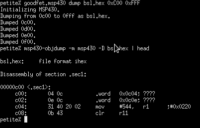
The security model of the BSL is a bit confusing. Upon connecting, you are required to present a password before reading, writing, or doing anything else that might affect the security of the device. You are, however, allowed to erase all of flash memory--including the info flash--to 0xFFFF. As this is traditionally the first command that you send upon connecting to a device, you will wipe all of the configuration data of a chip in programming it. Finding this problem is hellish, because the exact same code will work if programmed by JTAG and you quite often have not got JTAG handly if you intend to program everything by the BSL.
As part of the GoodFET project, I've forked TinyOS's tos-bsl client to add support for the MSP430F2xx. I've also implemented a "--dumpinfo" command for dumping info flash to a TI Text file. This file can be reflashed after the chip has been erased to restore its factory settings.
This output is in the TI Text format, which is easily converted to Intel-hex, but is a hell of a lot easier to write. Piping it into a file allows me to restore the contents of flash after erasure, and also to extract the configuration values which are used on this chip. Because the chips are similar physically, it turns out that the calibration values for one are often sufficient to program another. So by observing the model number (in big endian at 0x0FF0), I can guess in the absence of calibration values.
When I find the time, I intend to test a large quantity MSP430 chips to determine the exact tolerances of manufacturing, the variances of CALBC1_16MHZ and CALDCO_16MHZ, and the probability that a given unit will so drastically differ from these values that serial communications become impossible. For now, I've found that the hardwired values above seem to work for all recently acquired MSP430F2274, MSP430F2254, and MSP430F2618 microcontrollers when using the hardware UART at 115,200 bits per second. Further, the GoodFET firmware does not require a crystal when running on these chips.
The following is a description of the MSP430F2xx Info Flash, as well as my ugly--yet reliable--hack for initializing the DCO of MSP430F2xx chips after my use of the Serial Bootstrap Loader (BSL) has destroyed the contents of that flash on the GoodFET. This ought to be of use to anyone who wishes to make an MSP430 design without a crystal, as well as for anyone who has accidentally erased info flash.
The mask-ROM bootstrap loader, BSL, of the MSP430 chips is damned handy, despite some security concerns. It allows you to very quickly program a chip by the same USB/serial converter that you use to interface it with a computer, without any of the hassles of having to flash a bootloader onto the chip. In this article, I describe the way in which the MSP430F2xx flash can be accidentally corrupted by the bootloader, as well as a method for repairing that damage by backing up the info flash while the password is left as the default.
The MSP430F2xx family has another dandy feature, that clock configuration values need not be calibrated to an external clock, such as the 32KHz crystal of the older GoodFET models. Instead, configuration data is calculated at the factory and placed into info1 flash, a region of 256 bytes at 0x1000. Using this, code that would be rather complicated can become trivially simple.
The code that configures the clock is configured on the GoodFET with MSP430F1xx chips is too complicated for me to include here. By contrast, on the MSP430F2xx chips, it becomes just
void msp430_init_dco() {
  BCSCTL1 = CALBC1_16MHZ;
  DCOCTL = CALDCO_16MHZ;
}
The security model of the BSL is a bit confusing. Upon connecting, you are required to present a password before reading, writing, or doing anything else that might affect the security of the device. You are, however, allowed to erase all of flash memory--including the info flash--to 0xFFFF. As this is traditionally the first command that you send upon connecting to a device, you will wipe all of the configuration data of a chip in programming it. Finding this problem is hellish, because the exact same code will work if programmed by JTAG and you quite often have not got JTAG handly if you intend to program everything by the BSL.
As part of the GoodFET project, I've forked TinyOS's tos-bsl client to add support for the MSP430F2xx. I've also implemented a "--dumpinfo" command for dumping info flash to a TI Text file. This file can be reflashed after the chip has been erased to restore its factory settings.
petite%  goodfet.bsl --dumpinfo
MSP430 Bootstrap Loader Version: 1.39-goodfet-8
Use -h for help
Transmit default password ...
@1000
aa 55 ff 3f cd ab aa 55 34 12 ff ff aa 55
ff ff ff ff ff ff ff ff ff ff ff ff ff ff
ff ff ff ff ff ff ff ff ff ff ff ff ff ff
ff ff ff ff ff ff ff ff ff ff ff ff ff ff
ff ff ff ff ff ff ff ff ff ff ff ff ff ff
ff ff ff ff ff ff ff ff ff ff ff ff ff ff
ff ff ff ff ff ff ff ff ff ff ff ff ff ff
ff ff ff ff ff ff ff ff ff ff ff ff ff ff
ff ff ff ff ff ff ff ff ff ff ff ff ff ff
ff ff ff ff ff ff ff ff ff ff ff ff ff ff
ff ff ff ff ff ff ff ff ff ff ff ff ff ff
ff ff ff ff ff ff ff ff ff ff ff ff ff ff
ff ff ff ff ff ff ff ff ff ff ff ff ff ff
ff ff ff ff ff ff ff ff ff ff b4 85 fe 16
ff ff ff ff ff ff ff ff ff ff ff ff ff ff
ff ff ff ff ff ff ff ff 08 10 00 80 01 00
62 7f b2 0b e8 0d 98 7f 01 07 56 08 fe 08
ff ff ff ff ff ff ff ff 01 08 7f 8f 85 8e
74 8d c2 86
q

petite%
This output is in the TI Text format, which is easily converted to Intel-hex, but is a hell of a lot easier to write. Piping it into a file allows me to restore the contents of flash after erasure, and also to extract the configuration values which are used on this chip. Because the chips are similar physically, it turns out that the calibration values for one are often sufficient to program another. So by observing the model number (in big endian at 0x0FF0), I can guess in the absence of calibration values.
//! Initialize the MSP430 clock.
void msp430_init_dco() {
  if(CALBC1_16MHZ!=0xFF){
    //Clear DCL for BCL12
    DCOCTL = 0x00;
    //Info is intact, use it.
    BCSCTL1 = CALBC1_16MHZ;
    DCOCTL = CALDCO_16MHZ;
  }else{
    //Info is missing, guess at a good value.
    BCSCTL1 = 0x8f;   //CALBC1_16MHZ at 0x10f9
    DCOCTL = 0x7f;    //CALDCO_16MHZ at 0x10f8
  }
}
When I find the time, I intend to test a large quantity MSP430 chips to determine the exact tolerances of manufacturing, the variances of CALBC1_16MHZ and CALDCO_16MHZ, and the probability that a given unit will so drastically differ from these values that serial communications become impossible. For now, I've found that the hardwired values above seem to work for all recently acquired MSP430F2274, MSP430F2254, and MSP430F2618 microcontrollers when using the hardware UART at 115,200 bits per second. Further, the GoodFET firmware does not require a crystal when running on these chips.
Saturday, October 17, 2009
CC2430 Debug Protocol, First Notes
by Travis Goodspeed <travis at radiantmachines.com>
with thanks to Peter Kuhar

The following are my notes on the debugging mechanism of the CC2430 and other chips (such as the CC2530) from Chipcon using an 8051 core. These notes do not apply to the upcoming CC430. As most of this was written before I implemented the protocol, plenty of errata are likely to exist.
These notes are intended for those who wish to understand how the device is programmed, not for those who merely want a device programmer. See CCFlasher or the GoodFET for that.
Be sure to have a copy of SWRA124, which is the official documentation for this protocol.
Concerning pins, there are three related to debugging. Debug Data (DATA) is a synchronous, bidirectional data line. Debug Clock (DCLK) is its clock, but its edges also control when commands are interpreted, and it is crucial to initializing the chip's debugging unit. The third pin, !RST, puts the chip into a reset state when pulled low, but is also used to start the chip with the debugger enabled. The clock idles low, while !RST idles high. Data is posted during the rising edge, sampled during the falling edge. As there is no equivalent of the SPI !SS pin, it is necessary to dead-reckon commands; a command of incorrect length will cause unneighborly consequences.
To initialize the debugger, pull !RST low while sending two clock pulses on DCLK. It will look something like this,

The command byte 0x34 looks something like this,

Concerning commands, once the debugger has been initialized, the chip will accept a command byte, optionally followed by up to three additional parameter bytes. It will then reply with at least one byte, which might be discarded. Some commands reply with two bytes rather than one.
A command byte is composed of 8 bits. Bits 1 and 0--the least significant--contain the number of data bytes following the command. Bit 2 is labeled "return input byte to host", but it doesn't appear to be observed regularly by the documented examples. The remaining five bits specify the command itself.
Only twelve commands are described in the documentation, but either 16 or 32 commands are possible, depending upon whether the MSBit is variable or fixed to 0 as a sort of start bit.
These commands were chosen to be easy to implement in hardware. They include CHIP_ERASE, RD_CONFIG, WR_CONFIG, HALT, RESUME, GET_PC, and DEBUG_INSTR. There are no primitive commands for peeking or poking memory, nor for managing flash. Instead, macro commands are built up by using DEBUG_INSTR.
Concerning command execution, it is clear from the documentation that a command with no parameters begins to execute at the instant of the eighth falling debug clock edge. Multi-byte commands likely execute on multiple clock edges, each being the last falling edge of an instruction.
In any case, to debug a command, you simply send DEBUG_INSTR (0x54) summed with the length of the instruction, up to 3 bytes, then read a single byte reply. So to execute "NOP", send {0x55, 0x00}. Except for a jump, this will not affect the program counter.
Concerning memory access, there are no debugging commands to read or write memory. Instead, DEBUG_INSTR (0x54) is used to do the same. For example, to fetch from Data memory, first debug {0x90, AH, AL} to move the address into the data pointer. Then debug {0xE0, 0, 0} to MOVX from the data pointer into A. The 0's aren't part of the instruction, but they are necessary to give the device time to fetch the target of the pointer.
The is the code that fetches a byte from Data memory,

Concerning the writing of Flash, it is necessary to load a RAM buffer, then to copy that buffer into Flash by use of a short assembly script. Flash may only be erased in 2kB pages, and it may only be written as 32-bit words. The code that performs this is found on page 11 of SWRA124, and you'll find it in Data memory if you look hard enough after a programmer that doesn't cover its tracks.
You will find this code in the GoodFET source.
You will find the same code in RAM after programming.

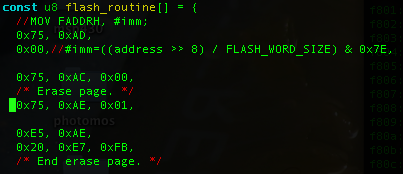
Concerning the protection of Code memory, there is a lock bit in a hidden page of Flash memory. By setting the lowest configuration bit (by WR_CONFIG), the lowest 2kB of flash memory will be mapped to a special information region. Clearing the least significant bit of the first byte will lock the chip, causing it to refuse debugging after a full-power reset. Access to debugging instructions can only be regained after executing a CHIP_ERASE, which erases all of Flash memory.
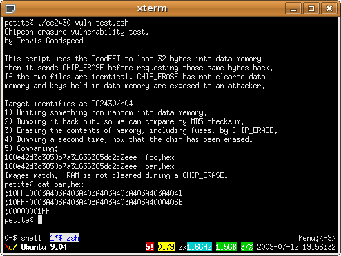
At Black Hat USA in August of 2009, I presented a paper entitled Extracting Keys from Second Generation Zigbee Chips. The vulnerability, demonstrated in the image below, is that Data memory is not cleared along with Flash memory during a CHIP_ERASE. By booting a wireless sensor, then erasing it, then dumping RAM, the attacker can find any keys which are stored within the unit. This works even for constant keys, as 8051 compilers will copy them into RAM in order to make C pointers consistent.
In implementing a debugger, it's also necessary to watch out for a minor bug. Upon connecting, be sure to DEBUG_INSTR a NOP so as to have the lock bit checked. Failure to do so might cause the lock bit to be misrepresented when checking the device's status.
In conclusion, the protocol is blessedly simple and the 16 pages of documentation are quite complete when supplemented with the CC2430 datasheet. I hope that these notes might allow you to implement the protocol with less of a headache than I have.
with thanks to Peter Kuhar
The following are my notes on the debugging mechanism of the CC2430 and other chips (such as the CC2530) from Chipcon using an 8051 core. These notes do not apply to the upcoming CC430. As most of this was written before I implemented the protocol, plenty of errata are likely to exist.
These notes are intended for those who wish to understand how the device is programmed, not for those who merely want a device programmer. See CCFlasher or the GoodFET for that.
Be sure to have a copy of SWRA124, which is the official documentation for this protocol.
Concerning pins, there are three related to debugging. Debug Data (DATA) is a synchronous, bidirectional data line. Debug Clock (DCLK) is its clock, but its edges also control when commands are interpreted, and it is crucial to initializing the chip's debugging unit. The third pin, !RST, puts the chip into a reset state when pulled low, but is also used to start the chip with the debugger enabled. The clock idles low, while !RST idles high. Data is posted during the rising edge, sampled during the falling edge. As there is no equivalent of the SPI !SS pin, it is necessary to dead-reckon commands; a command of incorrect length will cause unneighborly consequences.
To initialize the debugger, pull !RST low while sending two clock pulses on DCLK. It will look something like this,
The command byte 0x34 looks something like this,
Concerning commands, once the debugger has been initialized, the chip will accept a command byte, optionally followed by up to three additional parameter bytes. It will then reply with at least one byte, which might be discarded. Some commands reply with two bytes rather than one.
A command byte is composed of 8 bits. Bits 1 and 0--the least significant--contain the number of data bytes following the command. Bit 2 is labeled "return input byte to host", but it doesn't appear to be observed regularly by the documented examples. The remaining five bits specify the command itself.
Only twelve commands are described in the documentation, but either 16 or 32 commands are possible, depending upon whether the MSBit is variable or fixed to 0 as a sort of start bit.
These commands were chosen to be easy to implement in hardware. They include CHIP_ERASE, RD_CONFIG, WR_CONFIG, HALT, RESUME, GET_PC, and DEBUG_INSTR. There are no primitive commands for peeking or poking memory, nor for managing flash. Instead, macro commands are built up by using DEBUG_INSTR.
Concerning command execution, it is clear from the documentation that a command with no parameters begins to execute at the instant of the eighth falling debug clock edge. Multi-byte commands likely execute on multiple clock edges, each being the last falling edge of an instruction.
In any case, to debug a command, you simply send DEBUG_INSTR (0x54) summed with the length of the instruction, up to 3 bytes, then read a single byte reply. So to execute "NOP", send {0x55, 0x00}. Except for a jump, this will not affect the program counter.
Concerning memory access, there are no debugging commands to read or write memory. Instead, DEBUG_INSTR (0x54) is used to do the same. For example, to fetch from Data memory, first debug {0x90, AH, AL} to move the address into the data pointer. Then debug {0xE0, 0, 0} to MOVX from the data pointer into A. The 0's aren't part of the instruction, but they are necessary to give the device time to fetch the target of the pointer.
The is the code that fetches a byte from Data memory,
Concerning the writing of Flash, it is necessary to load a RAM buffer, then to copy that buffer into Flash by use of a short assembly script. Flash may only be erased in 2kB pages, and it may only be written as 32-bit words. The code that performs this is found on page 11 of SWRA124, and you'll find it in Data memory if you look hard enough after a programmer that doesn't cover its tracks.
You will find this code in the GoodFET source.
You will find the same code in RAM after programming.
Concerning the protection of Code memory, there is a lock bit in a hidden page of Flash memory. By setting the lowest configuration bit (by WR_CONFIG), the lowest 2kB of flash memory will be mapped to a special information region. Clearing the least significant bit of the first byte will lock the chip, causing it to refuse debugging after a full-power reset. Access to debugging instructions can only be regained after executing a CHIP_ERASE, which erases all of Flash memory.
At Black Hat USA in August of 2009, I presented a paper entitled Extracting Keys from Second Generation Zigbee Chips. The vulnerability, demonstrated in the image below, is that Data memory is not cleared along with Flash memory during a CHIP_ERASE. By booting a wireless sensor, then erasing it, then dumping RAM, the attacker can find any keys which are stored within the unit. This works even for constant keys, as 8051 compilers will copy them into RAM in order to make C pointers consistent.
In implementing a debugger, it's also necessary to watch out for a minor bug. Upon connecting, be sure to DEBUG_INSTR a NOP so as to have the lock bit checked. Failure to do so might cause the lock bit to be misrepresented when checking the device's status.
In conclusion, the protocol is blessedly simple and the 16 pages of documentation are quite complete when supplemented with the CC2430 datasheet. I hope that these notes might allow you to implement the protocol with less of a headache than I have.
Saturday, October 3, 2009
GoodFET30 Boards by Mail
Howdy y'all,
As anyone who has taken up my offer of a free GoodFET board can tell you, I've been terribly slow at shipping the things. Not only did I only send them while I was in stock, but I also had to have ample quantities of stamps and envelopes. Further, the envelopes were often lost in the mail do to my miscalculating postage (42¢≠44¢) or failing to properly pad each board. Add my travel schedule to the mix, and it was not uncommon for a neighbor to wait more than a month for his board to arrive.
To remedy this situation, I've arranged for blank boards to be shipped from Tennessee. Presently, the new GoodFET30 boards are in stock, and I'll order more panels as soon as these run out. To order one, just send a few bucks by Paypal to <sixtysixav at hotmail.com> along with a mailing address and a note that you'd like a GoodFET30. If you're broke or religiously opposed to Paypal, just send a neighborly request to my address below and I'll see that a free board goes your way.
Assembled units are coming, but don't expect them to be available before the new year.
N.B., do not forget to include your mailing address when ordering.
Thank you kindly,
--Travis Goodspeed
<travis at radiantmachines.com>
Sunday, September 13, 2009
GoodFET Firmware Distribution
by Travis Goodspeed <travis at radiantmachines.com>
Until recently, the GoodFET firmware was available only by source code through subversion. While I still expect all GoodFET users to be familiar with C, Unix, Subversion, and other such things, it is a bit much to ask each user to build the MSP430 cross compiler just to use the device. To that end, I'm implementing an automated testing server and firmware distribution system. The latest firmware images are now available by HTTP, free for any client to download and test. This article describes an early incarnation of this system.
To test each target, I've begun to fill a server in Philadelphia with GoodFET boards. Ideally, I'd like one of each GoodFET model matched to one of each target, but that collection has not yet been completed. In this screenshot below, the Chipcon and SPI Flash targets are being tested.
If the output contains anything different, the diff will show this and require manual intervention before an update may be published. These differences might be caused by a failed test, or they might be caused by a minor change, such as the amount of reported RAM consumption in the following screenshot.
To distribute these files, the Makefile in /packaging/ checks out a fresh copy of the code from subversion, builds and installs it to all attached boards, runs every available test case, and compares the results. If--any only if--all test cases match, the resulting intel hex files will be uploaded to http://goodfet.sourceforge.net/dist/. Clients may fetch these to update the targets, and I've added the "goodfet.bsl" client--a fork of tos-bsl-- to facilitate this upgrades.

Loadable modules will come next, along with some substantial changes to the GoodFET packet format that will allow for much larger blocks. I also hope to soon revamp MSP430 JTAG support, with support for quickly flashing 1xx and 5xx devices, as well as support for MSP430X (1xx and 4xx) devices.
As a final note, be sure to update your clients as well as your firmware. The packet format changes and other alterations might break compatibility of the new firmware with the old clients.
Until recently, the GoodFET firmware was available only by source code through subversion. While I still expect all GoodFET users to be familiar with C, Unix, Subversion, and other such things, it is a bit much to ask each user to build the MSP430 cross compiler just to use the device. To that end, I'm implementing an automated testing server and firmware distribution system. The latest firmware images are now available by HTTP, free for any client to download and test. This article describes an early incarnation of this system.
To test each target, I've begun to fill a server in Philadelphia with GoodFET boards. Ideally, I'd like one of each GoodFET model matched to one of each target, but that collection has not yet been completed. In this screenshot below, the Chipcon and SPI Flash targets are being tested.
If the output contains anything different, the diff will show this and require manual intervention before an update may be published. These differences might be caused by a failed test, or they might be caused by a minor change, such as the amount of reported RAM consumption in the following screenshot.
To distribute these files, the Makefile in /packaging/ checks out a fresh copy of the code from subversion, builds and installs it to all attached boards, runs every available test case, and compares the results. If--any only if--all test cases match, the resulting intel hex files will be uploaded to http://goodfet.sourceforge.net/dist/. Clients may fetch these to update the targets, and I've added the "goodfet.bsl" client--a fork of tos-bsl-- to facilitate this upgrades.
Loadable modules will come next, along with some substantial changes to the GoodFET packet format that will allow for much larger blocks. I also hope to soon revamp MSP430 JTAG support, with support for quickly flashing 1xx and 5xx devices, as well as support for MSP430X (1xx and 4xx) devices.
As a final note, be sure to update your clients as well as your firmware. The packet format changes and other alterations might break compatibility of the new firmware with the old clients.
Friday, September 4, 2009
State of the GoodFET
by Travis Goodspeed <travis at radiantmachines.com>
I shipped the last of the American GoodFET20 requests today. Please contact me if yours hasn't arrived. Orders to Europe will be sent next week, while I'm in Paris, Besançon, and Stockholm.
I'm now using the MSP430F2618 for GoodFET development, as it will run at 16MHz without a crystal. There are some bit errors on a few of these boards, owing to the accidental erasure of Info Flash by the bootloader. Until rebroadcasts are implemented, continue to construct your boards with the 1612 or 1611. The upcoming GoodFET30 will migrate the project entirely to the 2xx series, breaking compatibility with TI's firmware.
The Python clients are presently being refactored at the same time as the command structure is combined. Please contact me if you are interested in building a client for C# or Cocoa that will be easier to distribute.
Thanks to a generous EVK donation, MSP430X2 support is underway, which will allow such chips as the MSP430F5438 and the CC430 Zigbee SoC devices to be programmed. I've got the basics working, and full support for writing Flash memory ought to be ready rather soon.
I'm considering a plugin architecture that loads new modules into RAM, a GoodFET iPhone attachment, and all sorts of other crazy things. Comment with any feature requests below.
Thursday, August 20, 2009
The GoodFET's MSP430 Stack Depth
by Travis Goodspeed <travis at radiantmachines.com>
Today I'm stranded in Munich and unable to walk, so I thought it neighborly to measure the stack depth of the GoodFET's firmware in order to determine the minimal microcontroller necessary, reducing the material cost of each unit. This article ought to help those who wish to do the same.
The MSP430F1612 ($15 to $11) that I presently use is rather expensive, and a smaller, cheaper chip will likely suffice. While I don't expect the code to fit in the MSP430F2013 ($3 to $1.50), it's not unreasonable to assume that something like the MSP430F2274 ($5 to $3) would be a good choice.
To determine whether the Flash is sufficient is easy, as I can measure that by the size of the output image. make install reveals this to be 7566 bytes as of r79, which will comfortably fit in the MSP430F2254 (16KB) and 2274 (32KB) and doesn't come close to filling the 1612's 55KB of Flash.
Determining RAM usage is much more difficult, and likely better to be done in actual use than in simulation or by static analysis. I'm implementing this by adding two new commands to the Monitor application. The first, RAM_PATTERN (0x90), fills all of RAM with 0xBEEF, suiciding and resetting at the end. The second, RAM_DEPTH (0x91), measures how large this block of memory is. By running the first, then running several test cases, then running the second, I can accurately measure RAM usage, estimating the minimum required chip for the GoodFET firmware. RAM_PATTERN cannot simple be run at start because the GoodFET restarts each time a client connects.
RAM_PATTERN must know the entry point of the application in order to reset, as well as the start and end addresses of RAM. No care need be taken to avoid damaging the stack or global variables, as a reboot will obliterate and repopulate them anyways.
Looking at the linker script (trunk/firmware/ldscripts/161x.x), it can be seen that the RAM region is defined by data (rwx): ORIGIN = 0x1100, LENGTH = 0x1400, so it extends from 0x1100 to 0x2500. RAM_PATTERN simply writes 0xBEEF over this region, then calls asm("br &0xfffe") to reboot. Don't forget your pointer arithmetic: ++ on a pointer increments by the word size (2), not the integer address (1).
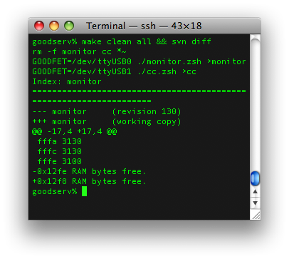
In any case, once these functions are working, it's a simple matter to measure RAM usage. As we know that 0x1400 bytes are available, we can fill with the pattern, then restart, then run code, and compare the number of available bytes. By the following log, you can see that 0x12b2 bytes are unused by the GoodFET firmware even after running the Chipcon test cases, or that 0x1400-0x12b2=0x14E=334 bytes of RAM are necessary.
Rounding that 334 byte measurement up a bit, it still ought to fit in the MSP430F2254's 512 bytes of RAM, with a pin-compatible upgrade available for the 2274 with 1 kilobyte of RAM. For comparison, the present hardware has 5K of RAM with the MSP430F1612 and 10K with the 1611.
Note that this lean behavior is only possible because the GoodFET's firmware is very flat and uses no dynamically allocated buffers. I will be running some more tests, and if they turn out to my liking, there's a good bet that the MSP430F2274 will be the basis of the GoodFET30.
Firmware compatibility between the two chips will require more creativity than the present scheme of a wacky linker script, as they are of different families. Seeing as how plenty of memory is left over, I could write firmware which identifies its host system and configures the I/O ports so as to run on either system from a single image. I don't think that I will do this, as incompatibilities in the I/O port choices would require complication of all I/O routines that could better be handled by preprocessor directives.
Today I'm stranded in Munich and unable to walk, so I thought it neighborly to measure the stack depth of the GoodFET's firmware in order to determine the minimal microcontroller necessary, reducing the material cost of each unit. This article ought to help those who wish to do the same.
The MSP430F1612 ($15 to $11) that I presently use is rather expensive, and a smaller, cheaper chip will likely suffice. While I don't expect the code to fit in the MSP430F2013 ($3 to $1.50), it's not unreasonable to assume that something like the MSP430F2274 ($5 to $3) would be a good choice.
To determine whether the Flash is sufficient is easy, as I can measure that by the size of the output image. make install reveals this to be 7566 bytes as of r79, which will comfortably fit in the MSP430F2254 (16KB) and 2274 (32KB) and doesn't come close to filling the 1612's 55KB of Flash.
Determining RAM usage is much more difficult, and likely better to be done in actual use than in simulation or by static analysis. I'm implementing this by adding two new commands to the Monitor application. The first, RAM_PATTERN (0x90), fills all of RAM with 0xBEEF, suiciding and resetting at the end. The second, RAM_DEPTH (0x91), measures how large this block of memory is. By running the first, then running several test cases, then running the second, I can accurately measure RAM usage, estimating the minimum required chip for the GoodFET firmware. RAM_PATTERN cannot simple be run at start because the GoodFET restarts each time a client connects.
RAM_PATTERN must know the entry point of the application in order to reset, as well as the start and end addresses of RAM. No care need be taken to avoid damaging the stack or global variables, as a reboot will obliterate and repopulate them anyways.
Looking at the linker script (trunk/firmware/ldscripts/161x.x), it can be seen that the RAM region is defined by data (rwx): ORIGIN = 0x1100, LENGTH = 0x1400, so it extends from 0x1100 to 0x2500. RAM_PATTERN simply writes 0xBEEF over this region, then calls asm("br &0xfffe") to reboot. Don't forget your pointer arithmetic: ++ on a pointer increments by the word size (2), not the integer address (1).
In any case, once these functions are working, it's a simple matter to measure RAM usage. As we know that 0x1400 bytes are available, we can fill with the pattern, then restart, then run code, and compare the number of available bytes. By the following log, you can see that 0x12b2 bytes are unused by the GoodFET firmware even after running the Chipcon test cases, or that 0x1400-0x12b2=0x14E=334 bytes of RAM are necessary.
petite% goodfet.monitor ramfill
petite% goodfet.monitor ramdepth
0x12c4 RAM bytes free.
petite% goodfet.monitor test
Performing monitor self-test.
Self-test complete.
petite% goodfet.cc test >>/dev/null
petite% goodfet.monitor ramdepth
0x12b2 RAM bytes free.
petite%
Rounding that 334 byte measurement up a bit, it still ought to fit in the MSP430F2254's 512 bytes of RAM, with a pin-compatible upgrade available for the 2274 with 1 kilobyte of RAM. For comparison, the present hardware has 5K of RAM with the MSP430F1612 and 10K with the 1611.
Note that this lean behavior is only possible because the GoodFET's firmware is very flat and uses no dynamically allocated buffers. I will be running some more tests, and if they turn out to my liking, there's a good bet that the MSP430F2274 will be the basis of the GoodFET30.
Firmware compatibility between the two chips will require more creativity than the present scheme of a wacky linker script, as they are of different families. Seeing as how plenty of memory is left over, I could write firmware which identifies its host system and configures the I/O ports so as to run on either system from a single image. I don't think that I will do this, as incompatibilities in the I/O port choices would require complication of all I/O routines that could better be handled by preprocessor directives.
Wednesday, August 19, 2009
Half-Blind Attacks, Source Barcelona
by Travis Goodspeed <travis at radiantmachines.com>
At the Third Usenix Workshop on Offensive Technologies, I presented Half-Blind Attacks: Mask ROM Bootloaders Are Dangerous with Aurélien Francillon. This paper describes the use of a stack overflow exploit to return into a random piece of flash memory, which often enough will elevate privileges before returning into the bootloader.
I'll be presenting the security-conference equivalent of this paper as a lecture at Source Barcelona on September 21 or 22, along with something new. I will bring both the demonstration hardware and plenty of GoodFET boards.
--Travis
Thursday, August 6, 2009
Extracting Keys from SoC Zigbee Chips
by Travis Goodspeed <travis at radiantmachines.com>
Last week, at Black Hat Briefings, I presented a short paper entitled Extracting Keys from Second Generation Zigbee Chips. Though brief, the paper is vitally important reading for anyone shipping a product with chips from Chipcon and Ember. The paper includes a method by which keys may be extracted from these chips, as well as a software method for defending Chipcon devices against the attack. All EM2xx chips are vulnerable, as are all of the 8051-based Chipcon radios, such as the CC2530. This is not the same as my attack against first generation, discrete radios.
Last week, at Black Hat Briefings, I presented a short paper entitled Extracting Keys from Second Generation Zigbee Chips. Though brief, the paper is vitally important reading for anyone shipping a product with chips from Chipcon and Ember. The paper includes a method by which keys may be extracted from these chips, as well as a software method for defending Chipcon devices against the attack. All EM2xx chips are vulnerable, as are all of the 8051-based Chipcon radios, such as the CC2530. This is not the same as my attack against first generation, discrete radios.
Wednesday, July 8, 2009
GoodFET HHV, Neighborcon Vegas, Taipei
Howdy neighbors,
I'll be bringing plenty of spare GoodFET boards to vegas, perhaps something new as well. If you'd like to build one in the Hardware Hacking Village, please bring the parts from the GoodFET11 BOM, with perhaps some extras to share. I've given away all of my assembled GoodFET boards, save the one I use for development, so don't expect to have any fun without soldering.
The Neighborcon Vegas CFP will come out soon. Neighborliness will be abounding during Black Hat Briefings for all those that need a break from the crowd or cannot afford the ticket. A shuttle should run regularly from Caesar's, and we'll have all sorts of neighborly workshops and competitions. The official announcement is being delayed to keep the crowd manageable, but it will definitely be happening.
I am in Taipei, R.O.C. for the next two weeks. Email me if you'd like to meet up for drinks, especially if you speak Chinese and can help me navigate the local electronics market.
New technical articles are coming soon, covering the debugging protocols of the MSP430 and Chipcon 8051 chips. MSP430X, MSP430X2, and others will follow as GoodFET support solidifies. Also some fixes for security vulnerabilities that I will be announcing at my Black Hat talk.
Cheers,
Travis Goodspeed
<travis at radiantmachines.com>
Friday, June 19, 2009
GoodFET MSP430 Tutorial
by Travis Goodspeed <travis at radiantmachines.com>
N.B., that this is quite outdated. See the GoodFET Tutorial for a more recent description.
This is a quick tutorial for using the GoodFET to program an MSP430. This should work for all classic MSP430 chips which support 4-wire JTAG, but it will not yet work with SpyBiWire or MSP430X2 chips, such as the MSP430F5xx and CC430. As these instructions will likely become dated very quickly, expect some surprises.
You will need a GoodFET board, complete with the clock crystal. Your workstation should have Python, Subversion, MSPGCC, and msp430-bsl installed. I assume below that you are using some form of Unix, but the software ought to be compatible with Cygwin. Those who are unfamiliar with Cygwin should wait for a GUI client that I'll release later this year.
If you are familiar with SMD soldering, email or catch me at a conference for a gratis board of the most recent revision.
Grab the entire project by running "svn co https://goodfet.svn.sourceforge.net/svnroot/goodfet". Future updates may be grabbed by "svn update".
CD to "goodfet/trunk/client" and run "sudo make link". This will link the client scripts to /usr/local/bin/, keeping the originals in the subversion directory to be easily updated. At this point, you can call up the "goodfet.msp430" command's usage by running it without parameters.

Change your directory to "goodfet/trunk/firmware", then run "make" to compile a firmware image. If there are errors, check your MSPGCC installation. Once compilation succeeds, run "make install" to load the firmware into the GoodFET device.
The "goodfet.msp430" script is a stand-in until I get around to writing a proper client. To dump a target's firmware, the usage is "/usr/local/bin/goodfet.msp430 dump $foo.hex [0x$start 0x$stop]". To dump the BSL, which resides in the region [0xC00,0xFFF],
As I collect BSL images, it would be neighborly of you to send the bsl.hex file my way. Dump with no range will dump all memory above 0x200, which is to say all memory that may be safely read without side effects.
The "erase" verb will mass erase all memory except for the DCO configuration. An erase is automatically performed prior to a flash.
The "flash" verb of this client will flash an image to the target board. Every address evenly divisible by 0x100 is printed as a sort of progress meter,
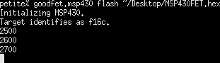
Each word is validated as it is written, making it easy to identify when writes go bad. In the photo below, words were miswritten from 0x2500 to 0x2508, but later words were written properly.

That's all, folks. Expect a slew of firmware updates for the GoodFET over the next few weeks, and perhaps a GUI client of some sort.
N.B., that this is quite outdated. See the GoodFET Tutorial for a more recent description.
This is a quick tutorial for using the GoodFET to program an MSP430. This should work for all classic MSP430 chips which support 4-wire JTAG, but it will not yet work with SpyBiWire or MSP430X2 chips, such as the MSP430F5xx and CC430. As these instructions will likely become dated very quickly, expect some surprises.
Prerequisites
You will need a GoodFET board, complete with the clock crystal. Your workstation should have Python, Subversion, MSPGCC, and msp430-bsl installed. I assume below that you are using some form of Unix, but the software ought to be compatible with Cygwin. Those who are unfamiliar with Cygwin should wait for a GUI client that I'll release later this year.
If you are familiar with SMD soldering, email or catch me at a conference for a gratis board of the most recent revision.
Subversion Checkout
Grab the entire project by running "svn co https://goodfet.svn.sourceforge.net/svnroot/goodfet". Future updates may be grabbed by "svn update".
Clients
CD to "goodfet/trunk/client" and run "sudo make link". This will link the client scripts to /usr/local/bin/, keeping the originals in the subversion directory to be easily updated. At this point, you can call up the "goodfet.msp430" command's usage by running it without parameters.
Firmware
Change your directory to "goodfet/trunk/firmware", then run "make" to compile a firmware image. If there are errors, check your MSPGCC installation. Once compilation succeeds, run "make install" to load the firmware into the GoodFET device.
Dumping an Image
The "goodfet.msp430" script is a stand-in until I get around to writing a proper client. To dump a target's firmware, the usage is "/usr/local/bin/goodfet.msp430 dump $foo.hex [0x$start 0x$stop]". To dump the BSL, which resides in the region [0xC00,0xFFF],
As I collect BSL images, it would be neighborly of you to send the bsl.hex file my way. Dump with no range will dump all memory above 0x200, which is to say all memory that may be safely read without side effects.
Erasing a Chip
The "erase" verb will mass erase all memory except for the DCO configuration. An erase is automatically performed prior to a flash.
Flashing an Image
The "flash" verb of this client will flash an image to the target board. Every address evenly divisible by 0x100 is printed as a sort of progress meter,
Each word is validated as it is written, making it easy to identify when writes go bad. In the photo below, words were miswritten from 0x2500 to 0x2508, but later words were written properly.
That's all, folks. Expect a slew of firmware updates for the GoodFET over the next few weeks, and perhaps a GUI client of some sort.
Saturday, June 13, 2009
Cold, Labless HNO3 Decapping Procedure
by Travis Goodspeed <travis at radiantmachines.com>
with thanks to Brooke Hill
The following are instructions and matching photos for removing the packaging of microchips without a proper chemical laboratory. Neither a hot plate nor a fume hood is required, and the only chemicals necessary are fuming nitric acid and acetone. The result is a bare die, with bonding wires. The bonding wires may then be removed and the die photographed using microscope.
The same as any author of a lay chemistry article, I must caution you to be very careful with the procedure that I describe. If you've no prior experience with chemistry, purchase an introductory book and study the safety instructions thoroughly. Nitric acid in these concentrations is nasty stuff, even when cold.
You will need two small vials with wax-paper seals, high-purity HNO3, acetone, tweezers, and a few pipettes. A fume hood is not required, as the reaction will be performed at room temperature. Safety glasses are recommended.
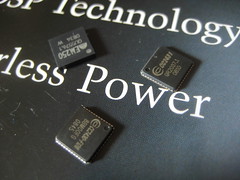
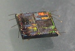
Surface mount chips are preferred for this method, as they have considerably less packaging to dissolve. I chose the CC2430, CC2431, and EM250 chips because they were handy, but also because I don't yet have die photographs of them.
Begin by dropping the chips to be decapped into a vial.
Then add nitric acid to cover the chips, plus a bit more. This will react slowly, rather than violently, but for safety's sake be damned sure never to look down any sort of glassware when mixing in a new reactant. You will see the reaction as small bubbles that come from the chip casing as it dissolves.
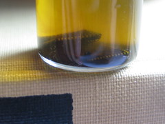
This will slowly turn the nitric acid from yellow to a dark green. Agitate it occasionally to ensure that all of the plastic gets a chance to break away.

Leave the mixture overnight, allowing the plastic sludge to settle to the bottom of the vial. The liquid above it is still-potent nitric acid, which may be skimmed off with a pipette. Save this in a second bottle for future use, but do not reintroduce it to your bottle of clean acid.

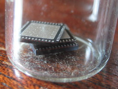
At this point, you've got a vial which contains a lot of plastic gunk and very little liquid. Flush it with water to remove the soluble gunk, then dump the remainder into a shot glass for sorting with tweezers. (Pick the chips up by their bonding wires, as you might scratch the surface.)

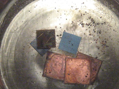
Once decapped, each die should be cleaned in acetone. For microscope photography, the bonding wires ought to also be plucked by tweezers.
with thanks to Brooke Hill
The following are instructions and matching photos for removing the packaging of microchips without a proper chemical laboratory. Neither a hot plate nor a fume hood is required, and the only chemicals necessary are fuming nitric acid and acetone. The result is a bare die, with bonding wires. The bonding wires may then be removed and the die photographed using microscope.
The same as any author of a lay chemistry article, I must caution you to be very careful with the procedure that I describe. If you've no prior experience with chemistry, purchase an introductory book and study the safety instructions thoroughly. Nitric acid in these concentrations is nasty stuff, even when cold.
Materials
You will need two small vials with wax-paper seals, high-purity HNO3, acetone, tweezers, and a few pipettes. A fume hood is not required, as the reaction will be performed at room temperature. Safety glasses are recommended.
Surface mount chips are preferred for this method, as they have considerably less packaging to dissolve. I chose the CC2430, CC2431, and EM250 chips because they were handy, but also because I don't yet have die photographs of them.
Procedure
Begin by dropping the chips to be decapped into a vial.
Then add nitric acid to cover the chips, plus a bit more. This will react slowly, rather than violently, but for safety's sake be damned sure never to look down any sort of glassware when mixing in a new reactant. You will see the reaction as small bubbles that come from the chip casing as it dissolves.
This will slowly turn the nitric acid from yellow to a dark green. Agitate it occasionally to ensure that all of the plastic gets a chance to break away.
Leave the mixture overnight, allowing the plastic sludge to settle to the bottom of the vial. The liquid above it is still-potent nitric acid, which may be skimmed off with a pipette. Save this in a second bottle for future use, but do not reintroduce it to your bottle of clean acid.
At this point, you've got a vial which contains a lot of plastic gunk and very little liquid. Flush it with water to remove the soluble gunk, then dump the remainder into a shot glass for sorting with tweezers. (Pick the chips up by their bonding wires, as you might scratch the surface.)
Result
Once decapped, each die should be cleaned in acetone. For microscope photography, the bonding wires ought to also be plucked by tweezers.
Friday, June 5, 2009
SPI Client Tutorial for the GoodFET
by Travis Goodspeed <travis at radiantmachines.com>
I've just confirmed that SPI support is functional on the GoodFET, but I've done so with my ugly-as-sin Python client. I'd much rather that neighborly souls write their own clients for this device. The following article describes the protocol by which this is done, as well as some snippets of the GoodFET firmware. The present code should be sufficient to write an AVR programmer, an interface for Chipcon radios, and all sorts of other neighborly things.
SPI is a synchronous, full-duplex serial protocol, which is an uptown way of saying that it has a clock and that bits are simultaneously transmitted and received. Whenever you transmit a byte, you are actually exchanging values of a register. Instead of start and stop bits, clocks are synchronized by the falling of the !SS (Slave Select) line, and then they remain synchronized by counting bits. Data is transmitted MSB-first, received LSB-first.
The GoodFET attaches by a USB serial port, one which is also used for programming. As the DTR, Data Terminal Ready, line is connected to the !RST pin of the GoodFET's microcontroller, you will find that the GoodFET turns off when you connect to it with Minicom or Hyperterminal, then turns back on when you disconnect! To remedy this, you must drop the DTR line low by using ioctl() in Posix C or your language's equivalent. This will boot the GoodFET, beginning a session.
The session itself will begin at9600 115200 8/N/1, although faster speeds will be supported in the near future. When you drop the line low, you will receive the three bytes {0x00, 0x7F, 0x00}. This is a GoodFET packet, and like all packets it follows the same, simple form. The first byte indicates the application, 0x00 being the Monitor. The other application that we will use is 0x01, SPI. The second byte is a verb, with all bytes less than 0x80 being generic verbs and all bytes higher being application-specific verbs. 0x7F means "OK" in every application. Other verbs include READ (0x00), WRITE (0x01), SETUP (0x10), and NOK (0x7E). A complete list of generic verbs is available in the Manual. The third byte, 0x00, indicates the number of data bytes that follow.
The GoodFET's protocol is transaction based, with every transaction after the first being begun by the host. It is recommended that your transmit function also automatically receive this reply. Further, any verb may have data attached. While the OK verb of the Monitor might never include data, your client had better accept whatever data it chooses to send your way.
Inside of the GoodFET, an application is merely a handler. All application present in the firmware are active simultaneously, and where it doesn't cause problems you may mix and match them. For example, you might wish to use the Monitor to manage the Test pin manually in order to implement an AVR programmer.
In any case, you can implement an SPI library through the GoodFET with only a few verbs. A sample session with commentary follows.
First, the host adjusts to 9600 8/N/1, then the device announces its presence.
D: {0x00 (Monitor), 0x7F (OK), 0x00 (0 bytes)}
The host calls the SETUP verb of the SPI application to configure the I/O pins.
H: {0x01 (SPI), 0x10 (SETUP), 0x00 (0 bytes)}
D: {0x01 (SPI), 0x10 (SETUP), 0x00 (0 bytes)}
At this point, the I/O pins are now properly configured. Pins 1, 2, 5, and 7 are now MISO, MOSI, !SS, and SCK. As the READ and WRITE verbs are interchangeable for SPI, the host may use either. If nothing is connected, the MISO pin's pullup resistor will ensure that the reply is always 0xFF.
H: {0x01 (SPI), 0x00 (READ), 0x01 (1 byte), 0xDE}
D: {0x01 (SPI), 0x00 (READ), 0x01 (1 byte), 0xFF}
H: {0x01 (SPI), 0x01 (WRITE), 0x01 (1 byte), 0xAD}
D: {0x01 (SPI), 0x01 (WRITE), 0x01 (1 byte), 0xFF}
If pins 1 (MISO) and 3 (MOSI) are bridged, the output (MOSI) will feed right back into the input (MISO), causing the output value to be returned.
H: {0x01 (SPI), 0x01 (WRITE), 0x01 (1 byte), 0x80}
D: {0x01 (SPI), 0x01 (WRITE), 0x01 (1 byte), 0x80}
If multiple SPI devices are chained together, such as in a gang programmer, data may be shifted through one into the other. To do this, make a ring with each MISO line connected to the next's MOSI, then perform a transaction of as many bytes as you have devices. This will cause !SS (Slave Select) to drop low, then all bytes will be shifted, then !SS will rise high to indicate the end of the transaction. The same is appropriate for registers in multiples of 8 bits, such as a 16 bit device. The first byte in the reply is the first byte to be received, so when ganging devices the bytes of the reply will need to have their order swapped.
H: {0x01 (SPI), 0x01 (WRITE), 0x02 (2 bytes), 0xDE, 0xAD}
D: {0x01 (SPI), 0x01 (WRITE), 0x02 (2 bytes), 0xBE, 0xEF}
A programmer/dumper for SPI EEPROMs could be written in short order, as could a command console for various Zigbee radio modules. The present application only supports SPI's master mode, but slave and sniffing support will be added at a later date.
A separate tutorial on extending the firmware will be available soon. If you'd like to get a head start, fork spi.c to make an I2C adapter. Email or catch me at a conference for a free board.
I've just confirmed that SPI support is functional on the GoodFET, but I've done so with my ugly-as-sin Python client. I'd much rather that neighborly souls write their own clients for this device. The following article describes the protocol by which this is done, as well as some snippets of the GoodFET firmware. The present code should be sufficient to write an AVR programmer, an interface for Chipcon radios, and all sorts of other neighborly things.
SPI is a synchronous, full-duplex serial protocol, which is an uptown way of saying that it has a clock and that bits are simultaneously transmitted and received. Whenever you transmit a byte, you are actually exchanging values of a register. Instead of start and stop bits, clocks are synchronized by the falling of the !SS (Slave Select) line, and then they remain synchronized by counting bits. Data is transmitted MSB-first, received LSB-first.
The GoodFET attaches by a USB serial port, one which is also used for programming. As the DTR, Data Terminal Ready, line is connected to the !RST pin of the GoodFET's microcontroller, you will find that the GoodFET turns off when you connect to it with Minicom or Hyperterminal, then turns back on when you disconnect! To remedy this, you must drop the DTR line low by using ioctl() in Posix C or your language's equivalent. This will boot the GoodFET, beginning a session.
The session itself will begin at
The GoodFET's protocol is transaction based, with every transaction after the first being begun by the host. It is recommended that your transmit function also automatically receive this reply. Further, any verb may have data attached. While the OK verb of the Monitor might never include data, your client had better accept whatever data it chooses to send your way.
Inside of the GoodFET, an application is merely a handler. All application present in the firmware are active simultaneously, and where it doesn't cause problems you may mix and match them. For example, you might wish to use the Monitor to manage the Test pin manually in order to implement an AVR programmer.
In any case, you can implement an SPI library through the GoodFET with only a few verbs. A sample session with commentary follows.
Transaction
First, the host adjusts to 9600 8/N/1, then the device announces its presence.
D: {0x00 (Monitor), 0x7F (OK), 0x00 (0 bytes)}
The host calls the SETUP verb of the SPI application to configure the I/O pins.
H: {0x01 (SPI), 0x10 (SETUP), 0x00 (0 bytes)}
D: {0x01 (SPI), 0x10 (SETUP), 0x00 (0 bytes)}
At this point, the I/O pins are now properly configured. Pins 1, 2, 5, and 7 are now MISO, MOSI, !SS, and SCK. As the READ and WRITE verbs are interchangeable for SPI, the host may use either. If nothing is connected, the MISO pin's pullup resistor will ensure that the reply is always 0xFF.
H: {0x01 (SPI), 0x00 (READ), 0x01 (1 byte), 0xDE}
D: {0x01 (SPI), 0x00 (READ), 0x01 (1 byte), 0xFF}
H: {0x01 (SPI), 0x01 (WRITE), 0x01 (1 byte), 0xAD}
D: {0x01 (SPI), 0x01 (WRITE), 0x01 (1 byte), 0xFF}
If pins 1 (MISO) and 3 (MOSI) are bridged, the output (MOSI) will feed right back into the input (MISO), causing the output value to be returned.
H: {0x01 (SPI), 0x01 (WRITE), 0x01 (1 byte), 0x80}
D: {0x01 (SPI), 0x01 (WRITE), 0x01 (1 byte), 0x80}
If multiple SPI devices are chained together, such as in a gang programmer, data may be shifted through one into the other. To do this, make a ring with each MISO line connected to the next's MOSI, then perform a transaction of as many bytes as you have devices. This will cause !SS (Slave Select) to drop low, then all bytes will be shifted, then !SS will rise high to indicate the end of the transaction. The same is appropriate for registers in multiples of 8 bits, such as a 16 bit device. The first byte in the reply is the first byte to be received, so when ganging devices the bytes of the reply will need to have their order swapped.
H: {0x01 (SPI), 0x01 (WRITE), 0x02 (2 bytes), 0xDE, 0xAD}
D: {0x01 (SPI), 0x01 (WRITE), 0x02 (2 bytes), 0xBE, 0xEF}
Ideas
A programmer/dumper for SPI EEPROMs could be written in short order, as could a command console for various Zigbee radio modules. The present application only supports SPI's master mode, but slave and sniffing support will be added at a later date.
A separate tutorial on extending the firmware will be available soon. If you'd like to get a head start, fork spi.c to make an I2C adapter. Email or catch me at a conference for a free board.
Friday, May 29, 2009
GoodFET11 Released
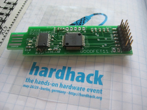
The GoodFET11 boards have arrived for HardHack in Berlin, where they were assembled earlier today. It was quite neighborly to see that intelligent people with steady hands, but no prior practice, had little trouble assembling the GoodFET's surface mount components.
GoodFET firmware ought to be functional in the next week or two, with I2C and the Chipcon debugging protocol as the first targets. Please contact me if you are interested in writing a client application in Python or another unix scripting language.
--Travis Goodspeed
<travis at radiantmachines.com>
Friday, May 22, 2009
Black Hat '09, Defcon 17
Howdy y'all,
I'll be taking a trip to Vegas this summer for Black Hat and Defcon. Abstracts below are as submitted to the conferences, and there will be a tool released, of the extra-neighborly sort, at Black Hat. I also expect to do some hands-on stuff at Defcon's hardware hacking village.
For Defcon,
Locally Exploiting Wireless Sensors
Wireless sensors are often built with a microcontroller and a radio chip, connected only by a SPI bus. The radio, not the MCU, is responsible for symmetrical cryptography of each packet. When the key is loaded, it is sent as cleartext over the SPI bus, and an attacker with local access can steal the key using a few syringe probes and readily available hardware. This attack and other local attacks against wireless sensor networks will be presented in detail, including a live demo of an AES128 key being extracted from an operational network. Following the conclusion of the lecture, audience members will be brought onstage to perform the attack themselves on various pieces of example hardware.
For Black Hat,
A 16 bit Rootkit and Second Generation Zigbee Chips
This lecture in two parts presents first a self-replicating rootkit for wireless sensors, then continues with recent research into the security of second generation Zigbee radio chips such as the CC2430/2431 and the EM250.
--Travis Goodspeed
<travis at radiantmachines.com>
Tuesday, May 19, 2009
MSP430 Challenge of May 2009
Howdy neighbors,
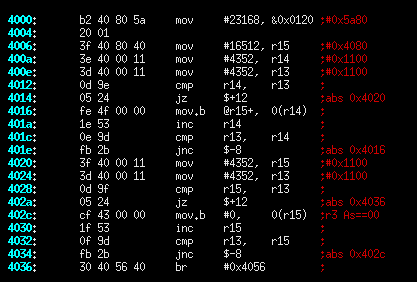
The following image is a piece of disassembled code that was compiled for the MSP430F1611. The code is found in many programs, but in this one it is accidentally vestigial as a result of a compiler bug. Please comment as to (1) which compiler generated the code, (2) what the code was intended to do, and (3) why the code is vestigial in the example, but might not be in another program. Translations to C or psuedocode and commented write-ups are also nice. The MSP430F1xx Family Guide might be handy if you're unfamiliar with the architecture.
I'll send a GoodFET board to the most insightful commentator, but as I send those boards out to anyone who asks, you're really only commenting for the neighborliness of it all. If I get enough replies, I'll post one of these each month.
Also, I saw a lot of good work on last month's Masked ROM Challenge while I was a Cleveland, but next to nothing has been sent my way. If you made significant progress, such as semi-automated extraction of the bits, please email me.
--Travis Goodspeed
<travis at radiantmachines.com>
HardHack and PH Neutral, Berlin

On April Fool's day, I jumped into my car and left Knoxville to wander the world in search of neighborliness. Now I find myself in Berlin, finishing up some projects and living on döner.
At the end of this month, I'll be giving a workshop at HardHack on Friday 29 May on the GoodFET project. No slideshow, no projector, just a good old fashioned, informal sermon on the design as we build a few USB JTAG adapters then program them. Sign-ups for the workshop are here.
The GoodFET is self-programmable by USB, so upgrading firmware requires no additional hardware. As this is surface-mount, you'll need to have a steady hand and good eyesight. I've ordered parts and boards for the GoodFET11, with the GoodFET10 as a backup if the boards don't arrive in time.
On Saturday 30 May at 15h00, I'll be presenting at PH Neutral. Everything about the talk is a surprise, except that it involves embedded systems.
--Travis Goodspeed
<travis at radiantmachines.com>
Friday, May 15, 2009
Microchip Zena Reversed
Howdy y'all,
Neighbor Joshua Wright has reverse engineered the Microchip Zena Zigbee sniffer's USB protocol, allowing packets to be dumped and channels to be hopped from Linux. Kismet support is the next step.
The EZ430RF2500 uses similar tricks in Windows with its HID driver, making Linux support quite difficult. If you have a Windows machine and are interested in doing the same to the RF2500 kit, please send an email my way, with a carbon copy to Josh.
--Travis
<travis at radiantmachines.com>
Wednesday, May 13, 2009
FET Firmware from MSP430.DLL
by Travis Goodspeed <travis at radiantmachines.com>
The firmware of the MSP430 FET is distributed for purposes of upgrades within MSP430.dll. In this brief article, I'll describe its location and a method for extraction.
All of these examples will use MSP430.dll with the following checksum. My previous FET articles have used a firmware image from the last revision of libMSP430.so, so addresses and code fragments will differ slightly.
f0685a0eca0545dfc542530afff8159f
A bit of quick searching reveals that the firmware of the MSP430 FET is contained within MSP430.dll as little-endian words at these addresses.
Bootloader code at offset of 0x1BFE8, region [0xF800,0xFFE0).
Application code at offset of 0x1EB38, region [0x2500,0xF7E0).
IVT at offset of 0x1BDBC, region [0xFFE0,0xFFFF].
That is, to recover the bootloader, copy 32 bytes (0x10000-0xFFE0=0x20) from the DLL at (0x1BDBC+0xFFE0=0x2BD9C) offset to the target MSP430 image at 0xFFE0.
Below are memory maps of my first attempt at extraction and an old EZ430 FET. It's clear that a lot of junk has been included by accident, which is why tabular entries, rather than regions should be used.


In addition to the large segments, there are also a few scattered bytes that form the lower IVT. (See Repurposing the TI EZ430U, Part 3 for an explanation of why there are two Interrupt Vector Tables.) Because the lower IVT is sparse, only those words which are not 0xFFFF are included. For example, the lower RESET vector--which, incidentally, is never read by the bootloader, in which the lower RESET is hard-coded--resides at 0xF7FE and points to 0x2502.
Searching MSP430.DLL for the interrupt vector, "02 25", yields a few results, one of which is "fe f7 d9 02 02 25". That's quite clearly an entry in a table of some sort. Searching around it yields a few more entries.
By this point is should be clear that while it might be possible to extract the different fragments of the firmware manually, it would by much nicer to dump the whole damned thing as a table. This can be done.
Each entry is of the form {adr, len, data} where adr is the 16-bit address of the fragment within the firmware image, len is the length of the data in 16-bit words, and data is a collection of 16-bit words as little-endian. Following one entry is another, ending with an invalid address. (Anything less than 0x200 is I/O, anything less than 0x2500 is not flash.) Adding 4+(len<<1) to an entry's pointer gives the next entry.
Using this technique and finding an initial entry point of 0x21036, I generated a dump that produces the following image (left) as compared to the previous attempt (right).

The new attempt contains everything important, including a few bytes which were missed in the first attempt. It also lacks all of the vestigial bytes that got roped in by the previous method. Further, as each binary is defined by a single entry point, it shouldn't be terribly difficult to search for the entry point in order to generically dump any version of the library.
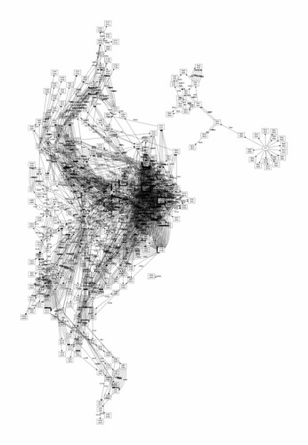
This cleanliness is confirmed by the callgraph below, which properly shows no function calls between the bootloader (right) and the application (left). (Branches are not graphed.)
The MSP430 Flash Emulation Tool's firmware is available for free download in MSP430.DLL, and anyone wishing to experiment with it need only download the library and extract the code.
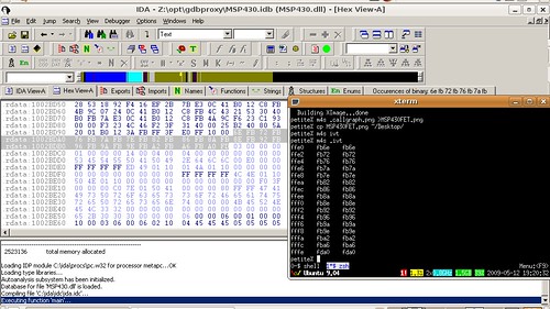
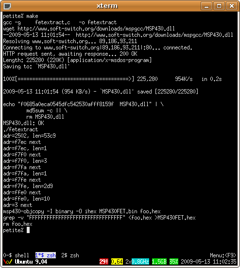
A hastily written extraction utility can be found by subversion. A screenshot follows.
svn co https://goodfet.svn.sourceforge.net/svnroot/goodfet/contrib/fetextract
The firmware of the MSP430 FET is distributed for purposes of upgrades within MSP430.dll. In this brief article, I'll describe its location and a method for extraction.
Firmware as Regions
All of these examples will use MSP430.dll with the following checksum. My previous FET articles have used a firmware image from the last revision of libMSP430.so, so addresses and code fragments will differ slightly.
f0685a0eca0545dfc542530afff8159f
A bit of quick searching reveals that the firmware of the MSP430 FET is contained within MSP430.dll as little-endian words at these addresses.
Bootloader code at offset of 0x1BFE8, region [0xF800,0xFFE0).
Application code at offset of 0x1EB38, region [0x2500,0xF7E0).
IVT at offset of 0x1BDBC, region [0xFFE0,0xFFFF].
That is, to recover the bootloader, copy 32 bytes (0x10000-0xFFE0=0x20) from the DLL at (0x1BDBC+0xFFE0=0x2BD9C) offset to the target MSP430 image at 0xFFE0.
Below are memory maps of my first attempt at extraction and an old EZ430 FET. It's clear that a lot of junk has been included by accident, which is why tabular entries, rather than regions should be used.
In addition to the large segments, there are also a few scattered bytes that form the lower IVT. (See Repurposing the TI EZ430U, Part 3 for an explanation of why there are two Interrupt Vector Tables.) Because the lower IVT is sparse, only those words which are not 0xFFFF are included. For example, the lower RESET vector--which, incidentally, is never read by the bootloader, in which the lower RESET is hard-coded--resides at 0xF7FE and points to 0x2502.
Searching MSP430.DLL for the interrupt vector, "02 25", yields a few results, one of which is "fe f7 d9 02 02 25". That's quite clearly an entry in a table of some sort. Searching around it yields a few more entries.
Firmware as a Table
By this point is should be clear that while it might be possible to extract the different fragments of the firmware manually, it would by much nicer to dump the whole damned thing as a table. This can be done.
Each entry is of the form {adr, len, data} where adr is the 16-bit address of the fragment within the firmware image, len is the length of the data in 16-bit words, and data is a collection of 16-bit words as little-endian. Following one entry is another, ending with an invalid address. (Anything less than 0x200 is I/O, anything less than 0x2500 is not flash.) Adding 4+(len<<1) to an entry's pointer gives the next entry.
Using this technique and finding an initial entry point of 0x21036, I generated a dump that produces the following image (left) as compared to the previous attempt (right).
The new attempt contains everything important, including a few bytes which were missed in the first attempt. It also lacks all of the vestigial bytes that got roped in by the previous method. Further, as each binary is defined by a single entry point, it shouldn't be terribly difficult to search for the entry point in order to generically dump any version of the library.
This cleanliness is confirmed by the callgraph below, which properly shows no function calls between the bootloader (right) and the application (left). (Branches are not graphed.)
The Code
The MSP430 Flash Emulation Tool's firmware is available for free download in MSP430.DLL, and anyone wishing to experiment with it need only download the library and extract the code.
A hastily written extraction utility can be found by subversion. A screenshot follows.
svn co https://goodfet.svn.sourceforge.net/svnroot/goodfet/contrib/fetextract
Saturday, May 9, 2009
UART Sniffing Notes
by Travis Goodspeed <travis at radiantmachines.com>
concerning a collaboration with Reilly Grant.
The following are some brief notes on asynchronous serial traffic, how to decipher it, and how to identify a baud rate when a scope is unavailable.
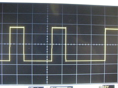

Of the two waveforms above, the first is RS232 and the second is TTL-level serial. They are on opposite sides of a MAX232 level-converter, and the images have been scaled to show the same point in the transmission, which is inverted and amplified by the MAX232. Here, the TTL line is +5V for a 1 and 0V for a 0. The RS232 line is -10V for a 0 and +10V for a 1.
In decoding serial traffic, it is important to recognize that the least significant bit is transmitted first, and that it is preceded by a start bit of 0. Following the most significant bit will be an optional parity bit and stop bit of 1. Thus, 0xEE would be
111111110011101111111111
where the bold portion is the data byte and the surrounding ones are the idle state. For practice, draw arbitrary bytes on paper, both as RS232 and as TTL-level. Further, note that the exact end of the byte is not immediately clear, and can only be found by matching timing from the starting 0 bit.
Here is a photograph of a few bytes.
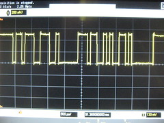
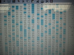
When decoding serial traffic, it is crucially important to do so at the proper rate. It is for this reason that the standard baud rates have been decided upon. The traffic above was received at roughly, but not quite exactly, twice its baud rate. Note--by clicking the image for a better view--how common bytes of 0xFF and 0x00 are, as well as how rare a byte containing just a single 1 or 0 in isolation is.
Once sniffing traffic on the proper order of magnitude, it is often the case that a smart card reader will not be using exactly the same timing. As timing is synchronized not to a clock, but to a start bit, the less significant bits will be correct with errors being found in the more significant bits. For example, "0x3B 0x02" might be mistakenly read as "0x9B 0x82" if the transmission is being sniffed at a slower rate than the actual. This is because the stop bits are being misinterpreted as most-significant bits. (10,400 baud being sniffed at 9600 baud, in this case.)
To determine the next guess from an incorrect read without a scope, draw the misinterpreted byte and the correct byte of graph paper, comparing them. Shown below are 0x3B and 0x9B, click on the image for annotations.

Unfortunately, Unix was not designed with odd baud rates in mind, and the Linux solution isn't terribly elegant either. In short, you must configure the port to run at 38,400 baud and override that baud rate with a manually chosen clock divider. For details, see the setserial documentation, looking at the spd_cust option. Further complicated matters, spd_cust doesn't seem to work with the FTDI usb/serial chip. If you can get the chip to work at an odd rate, please post a comment with details.
Automatically identifying the baud rate isn't terribly hard for a microcontroller, which can watch traffic to measure the bit width and adjust its reception appropriately. At some point, I'll write firmware for the MSP430 to do just that.
concerning a collaboration with Reilly Grant.
The following are some brief notes on asynchronous serial traffic, how to decipher it, and how to identify a baud rate when a scope is unavailable.
RS232, TTL UART Waveforms
Of the two waveforms above, the first is RS232 and the second is TTL-level serial. They are on opposite sides of a MAX232 level-converter, and the images have been scaled to show the same point in the transmission, which is inverted and amplified by the MAX232. Here, the TTL line is +5V for a 1 and 0V for a 0. The RS232 line is -10V for a 0 and +10V for a 1.
In decoding serial traffic, it is important to recognize that the least significant bit is transmitted first, and that it is preceded by a start bit of 0. Following the most significant bit will be an optional parity bit and stop bit of 1. Thus, 0xEE would be
111111110011101111111111
where the bold portion is the data byte and the surrounding ones are the idle state. For practice, draw arbitrary bytes on paper, both as RS232 and as TTL-level. Further, note that the exact end of the byte is not immediately clear, and can only be found by matching timing from the starting 0 bit.
Here is a photograph of a few bytes.
Double Timing
When decoding serial traffic, it is crucially important to do so at the proper rate. It is for this reason that the standard baud rates have been decided upon. The traffic above was received at roughly, but not quite exactly, twice its baud rate. Note--by clicking the image for a better view--how common bytes of 0xFF and 0x00 are, as well as how rare a byte containing just a single 1 or 0 in isolation is.
Close Timing
Once sniffing traffic on the proper order of magnitude, it is often the case that a smart card reader will not be using exactly the same timing. As timing is synchronized not to a clock, but to a start bit, the less significant bits will be correct with errors being found in the more significant bits. For example, "0x3B 0x02" might be mistakenly read as "0x9B 0x82" if the transmission is being sniffed at a slower rate than the actual. This is because the stop bits are being misinterpreted as most-significant bits. (10,400 baud being sniffed at 9600 baud, in this case.)
To determine the next guess from an incorrect read without a scope, draw the misinterpreted byte and the correct byte of graph paper, comparing them. Shown below are 0x3B and 0x9B, click on the image for annotations.
Unfortunately, Unix was not designed with odd baud rates in mind, and the Linux solution isn't terribly elegant either. In short, you must configure the port to run at 38,400 baud and override that baud rate with a manually chosen clock divider. For details, see the setserial documentation, looking at the spd_cust option. Further complicated matters, spd_cust doesn't seem to work with the FTDI usb/serial chip. If you can get the chip to work at an odd rate, please post a comment with details.
Automation
Automatically identifying the baud rate isn't terribly hard for a microcontroller, which can watch traffic to measure the bit width and adjust its reception appropriately. At some point, I'll write firmware for the MSP430 to do just that.
Thursday, April 30, 2009
Improving the MSP430 FET
by Travis Goodspeed <travis at radiantmachines.com>
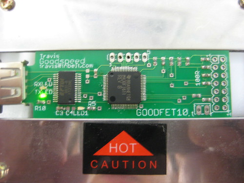
To celebrate 4/30 day, I am happy to announce my own variant of the MSP430 FET debugger. My variant is compatible with a patched version of the original firmware, but my goal is to eventually have open firmware as well.
For an overview of the internal functioning of the original FET, see my three part series on Repurposing the EZ430, or torrent my 25C3 lecture on the same topic.
For the purposes of this discussion, a FET is any Flash Emulation Tool containing an MSP430F1612, including the FET UIF and EZ430 debuggers. The parallel-port FET operates differently and is outside the bounds of this discussion.
To follow along with this discussion, be sure to print the FET schematics from the relevant TI application notes. The FET UIF's schematic can be found on page 64 of SLAU138K. Version 1.0 of the EZ430U can found on page 12 of SLAU176B, while Version 2.0 can be found on page 13 of SLAU227B. As I've likely made a few mistakes in the write-up, please kindly inform me of them.
All present FETs use the TUSB3410 usb to serial converter. Support for this chip is a pain in Linux, with kernel module requirements varying often. It's so bad that I keep a script in my private svn repository for fixing support as quickly as possible, and despite the recent appearance of open FET clients, using them on an obscure operating system is impossible without kernel support.
Internally, the '3410 is an 8051 microcontroller with a USB 2.0 Full Speed (12Mb/s) peripheral and a single UART. The traditional FET and most other devices use this chip with its default usb/serial firmware, but the second-generation EZ430 firmware uses various tricks to make a second, bit-banged, asynchronous serial port to the debugging target. On Windows, this leads to reliability issues, and on Linux, this leads to utter incompatibility. The '3410 also requires several external components, complicated the design and making hand soldering less feasible.
The FT232R from FTDI is a perfect replacement. It is available in an SSOP28 package for easy soldering, every operating system on Earth supports it, and its only external components are decoupling capacitors.
The MSP430 Bootstrap Loader (BSL) and I have had some good times together. While I still consider it to be a security risk for locked devices, it's damned handy for an unlocked board such as the FET. Likely for historical reasons, the BSL runs on P1.1 and P2.2, rather than the hardware UART pins. It also requires a special reset sequence, in which the RTS and DTS serial lines are connected to the RST and TCK pins.
Early revisions of the FET did not connect the BSL I/O pins, making the software bootloader that I describe in my articles on the EZ430 necessary. (The FET and first-generation EZ430 share a flash bootloader, while the second-generation EZ430 has a different, larger bootloader.) While later hardware revisions of the UIF connect the BSL pins, I've not seen the masked-ROM BSL used in practice. My design supports the BSL, preventing bricking and allowing for TI's firmware and open firmware to be exchanged at a whim.
To program the board by BSL, use tos-bsl with the --invert-reset and --invert-test switches.
The MSP430F1612 was chosen for compatibility with the original FET. It has 55K of flash and 5K of RAM. Alternately, the MSP430F1611 with an identical footprint might be used for applications which require additional RAM but are willing to use less flash, at the expense of compatibility with the original chip. (MSP430 firmware grows upward from the bottom of flash memory, making it easy to port code from a device with less flash to a device with more, but difficult to port in the opposite direction.)
All custom firmware should be compiled to run in the intersection of memory of the two chips. In that way, most applications will run on either chip, with only those that need more stack depth requiring the 1611 and only those requiring more flash memory requiring the 1612.
The MSP430 supports both high-speed and low-speed crystals, with the low-speed crystal's frequency being multiplied. Stable timing is not necessary for synchronous protocols such as JTAG or Spy-Bi-Wire, but only for asynchronous serial communication. While the EZ430 and FET firmwares both demand high-frequency crystals for absurdly high serial baud rates, I expect to reduce the data rate and source an external low-frequency crystal to reduce the parts count.
It is also possible to use bit-banged serial, or to call bit-banging serial routines from the bootloader (BSL) ROM. The BSL's code is particularly elegant because it resyncs the timing with the 0x80 SYN byte. This byte in 8/E/1 (8 bits, Event parity, 1 stop bit) appears as 8 marks surrounded by spaces, so rather than being read it is measured. The measured width is right shifted three times to get a bit's width, then once more for a half-bit. This measurement is used to bit-bang one transaction, then a new measurement is made for the next transaction. In this manner, even without a crystal, the BSL is able to perform fast, reliable serial communication in spite of clock drift. By calling this code--which is already resident in each chip--crystal-free operation is possible.
A high-frequency crystal is required to run unpatched variants of TI's firmware, but I've decided against including one in the design at this stage. Perhaps this will change in the future.
The first four pins of P5 are used as JTAG and SBW I/O. Starting with P5.0 and continuing to P5.3, they are TMS, TDI, TDO, and TCK. I've chosen to omit the FET UIF's optical isolation in favor of the EZ430's simpler protection, which consists of 47K pull up resistors and 100R current-limiting resistors. Unlike the EZ430, which only support spy-bi-wire, my design has a full 14-pin JTAG connector.
The above image is the firmware of an EZ430U FET, generated by msp430static. 0x0000 is the bottom left corner, 0xFF00 the top left, and 0xFFFF the top right. Blue represents the target of an immediate pointer, black is empty flash memory, red is potentially executable code, and grey is information which is certainly not executable.
The image is composed of two parts. The upper red region is a bootloader which is used to reflash the chip, while the lower region does the actual work. As compilers ship with firmware upgrades, it is not necessary to distribute any copyrighted code. A replacement bootloader could accept a firmware upgrade, then patch it, while retaining software compatibility. More information on the bootloader can be found in Part 3 of my series on repurposing the TI EZ430U.
Ideally, replacement firmware will be written for various applications, beyond MSP430 debugging. The same hardware could program competing microcontrollers, serial eeproms, FPGAs, and all sort of other things in the same way that the Hackaday Bus Pirate does.
So far as replacement firmware for debugging MSP430 chips goes, documentation is slim. Enough of the JTAG protocol has been documented to implement programming, but the setting of hardware breakpoints and other advanced features are not described by any public documentation. Custom firmware is not yet functional, but that ought to change in the near future.
The red board variants of the EZ430, those shipping with the RF kits, use drastically different firmware to facilitate a second serial port that connects to the target board. This breaks Linux compatibility, requiring firmware of both the MSP430 and the CAT24 EEPROM of the board to be downgraded.
To support low voltage serial communications, I brought out the second UART of the board's MSP430 to test points. This might also be used for timing attacks or similar things. Series and pull-up resistors would be nice on these lines, but they were omitted in the first design.
I've ordered a panel of the first revision, GOODFET10, and I'll send a board to anyone who is willing to assemble the device and help construct its firmware. Schematics, gerbers, and construction details have been posted to http://goodfet.sourceforge.net/, and "hello world" firmware has already been committed to the subversion repository.
To celebrate 4/30 day, I am happy to announce my own variant of the MSP430 FET debugger. My variant is compatible with a patched version of the original firmware, but my goal is to eventually have open firmware as well.
For an overview of the internal functioning of the original FET, see my three part series on Repurposing the EZ430, or torrent my 25C3 lecture on the same topic.
For the purposes of this discussion, a FET is any Flash Emulation Tool containing an MSP430F1612, including the FET UIF and EZ430 debuggers. The parallel-port FET operates differently and is outside the bounds of this discussion.
To follow along with this discussion, be sure to print the FET schematics from the relevant TI application notes. The FET UIF's schematic can be found on page 64 of SLAU138K. Version 1.0 of the EZ430U can found on page 12 of SLAU176B, while Version 2.0 can be found on page 13 of SLAU227B. As I've likely made a few mistakes in the write-up, please kindly inform me of them.
FT232 for TUSB3410
All present FETs use the TUSB3410 usb to serial converter. Support for this chip is a pain in Linux, with kernel module requirements varying often. It's so bad that I keep a script in my private svn repository for fixing support as quickly as possible, and despite the recent appearance of open FET clients, using them on an obscure operating system is impossible without kernel support.
Internally, the '3410 is an 8051 microcontroller with a USB 2.0 Full Speed (12Mb/s) peripheral and a single UART. The traditional FET and most other devices use this chip with its default usb/serial firmware, but the second-generation EZ430 firmware uses various tricks to make a second, bit-banged, asynchronous serial port to the debugging target. On Windows, this leads to reliability issues, and on Linux, this leads to utter incompatibility. The '3410 also requires several external components, complicated the design and making hand soldering less feasible.
The FT232R from FTDI is a perfect replacement. It is available in an SSOP28 package for easy soldering, every operating system on Earth supports it, and its only external components are decoupling capacitors.
Bootstrap Loader
The MSP430 Bootstrap Loader (BSL) and I have had some good times together. While I still consider it to be a security risk for locked devices, it's damned handy for an unlocked board such as the FET. Likely for historical reasons, the BSL runs on P1.1 and P2.2, rather than the hardware UART pins. It also requires a special reset sequence, in which the RTS and DTS serial lines are connected to the RST and TCK pins.
Early revisions of the FET did not connect the BSL I/O pins, making the software bootloader that I describe in my articles on the EZ430 necessary. (The FET and first-generation EZ430 share a flash bootloader, while the second-generation EZ430 has a different, larger bootloader.) While later hardware revisions of the UIF connect the BSL pins, I've not seen the masked-ROM BSL used in practice. My design supports the BSL, preventing bricking and allowing for TI's firmware and open firmware to be exchanged at a whim.
To program the board by BSL, use tos-bsl with the --invert-reset and --invert-test switches.
MSP430F1612/1611
The MSP430F1612 was chosen for compatibility with the original FET. It has 55K of flash and 5K of RAM. Alternately, the MSP430F1611 with an identical footprint might be used for applications which require additional RAM but are willing to use less flash, at the expense of compatibility with the original chip. (MSP430 firmware grows upward from the bottom of flash memory, making it easy to port code from a device with less flash to a device with more, but difficult to port in the opposite direction.)
All custom firmware should be compiled to run in the intersection of memory of the two chips. In that way, most applications will run on either chip, with only those that need more stack depth requiring the 1611 and only those requiring more flash memory requiring the 1612.
Crystals
The MSP430 supports both high-speed and low-speed crystals, with the low-speed crystal's frequency being multiplied. Stable timing is not necessary for synchronous protocols such as JTAG or Spy-Bi-Wire, but only for asynchronous serial communication. While the EZ430 and FET firmwares both demand high-frequency crystals for absurdly high serial baud rates, I expect to reduce the data rate and source an external low-frequency crystal to reduce the parts count.
It is also possible to use bit-banged serial, or to call bit-banging serial routines from the bootloader (BSL) ROM. The BSL's code is particularly elegant because it resyncs the timing with the 0x80 SYN byte. This byte in 8/E/1 (8 bits, Event parity, 1 stop bit) appears as 8 marks surrounded by spaces, so rather than being read it is measured. The measured width is right shifted three times to get a bit's width, then once more for a half-bit. This measurement is used to bit-bang one transaction, then a new measurement is made for the next transaction. In this manner, even without a crystal, the BSL is able to perform fast, reliable serial communication in spite of clock drift. By calling this code--which is already resident in each chip--crystal-free operation is possible.
A high-frequency crystal is required to run unpatched variants of TI's firmware, but I've decided against including one in the design at this stage. Perhaps this will change in the future.
I/O Pins
The first four pins of P5 are used as JTAG and SBW I/O. Starting with P5.0 and continuing to P5.3, they are TMS, TDI, TDO, and TCK. I've chosen to omit the FET UIF's optical isolation in favor of the EZ430's simpler protection, which consists of 47K pull up resistors and 100R current-limiting resistors. Unlike the EZ430, which only support spy-bi-wire, my design has a full 14-pin JTAG connector.
Firmware, Old
The above image is the firmware of an EZ430U FET, generated by msp430static. 0x0000 is the bottom left corner, 0xFF00 the top left, and 0xFFFF the top right. Blue represents the target of an immediate pointer, black is empty flash memory, red is potentially executable code, and grey is information which is certainly not executable.
The image is composed of two parts. The upper red region is a bootloader which is used to reflash the chip, while the lower region does the actual work. As compilers ship with firmware upgrades, it is not necessary to distribute any copyrighted code. A replacement bootloader could accept a firmware upgrade, then patch it, while retaining software compatibility. More information on the bootloader can be found in Part 3 of my series on repurposing the TI EZ430U.
Firmware, New
Ideally, replacement firmware will be written for various applications, beyond MSP430 debugging. The same hardware could program competing microcontrollers, serial eeproms, FPGAs, and all sort of other things in the same way that the Hackaday Bus Pirate does.
So far as replacement firmware for debugging MSP430 chips goes, documentation is slim. Enough of the JTAG protocol has been documented to implement programming, but the setting of hardware breakpoints and other advanced features are not described by any public documentation. Custom firmware is not yet functional, but that ought to change in the near future.
Second Serial
The red board variants of the EZ430, those shipping with the RF kits, use drastically different firmware to facilitate a second serial port that connects to the target board. This breaks Linux compatibility, requiring firmware of both the MSP430 and the CAT24 EEPROM of the board to be downgraded.
To support low voltage serial communications, I brought out the second UART of the board's MSP430 to test points. This might also be used for timing attacks or similar things. Series and pull-up resistors would be nice on these lines, but they were omitted in the first design.
Availability
I've ordered a panel of the first revision, GOODFET10, and I'll send a board to anyone who is willing to assemble the device and help construct its firmware. Schematics, gerbers, and construction details have been posted to http://goodfet.sourceforge.net/, and "hello world" firmware has already been committed to the subversion repository.
Friday, April 17, 2009
Notacon Masked ROM Challenge
Here at Notacon 6 in Cleveland, I'm having a competition involving the decoding of the MSP430F22x4's masked BSL ROM. The ROM, pictured below, begins with "0c06; 0c1e; 3fff; 40b2; a540; 012c; 90b2; ffde;" and ends with (in reverse order) "62b1; 0401; 0102; 0000; 0000; 0000; 4040; 27f2; ffff; ffff; ffff; ffff;".
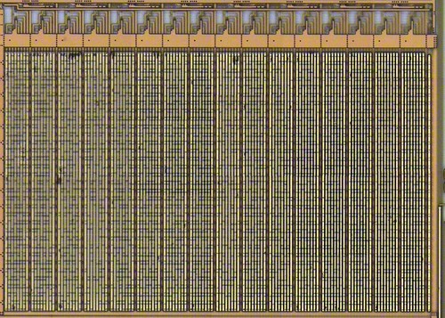
Begin by downloading the high resolution version of the image, then marking it like so.
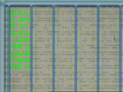
The first person to bring me a method for converting addresses to physical locations and back will win a Hack-A-Day Bus Pirate kit. A second kit will be given to the first person to bring me a script for generating correct bits from a binary (or Intel Hex) dump of the ROM.
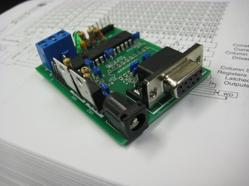
Hints will be given during my lecture, "Fun with the MSP430", Saturday at noon.
--Travis Goodspeed
<travis at radiantmachines.com>
Begin by downloading the high resolution version of the image, then marking it like so.
The first person to bring me a method for converting addresses to physical locations and back will win a Hack-A-Day Bus Pirate kit. A second kit will be given to the first person to bring me a script for generating correct bits from a binary (or Intel Hex) dump of the ROM.
Hints will be given during my lecture, "Fun with the MSP430", Saturday at noon.
--Travis Goodspeed
<travis at radiantmachines.com>
Friday, March 27, 2009
An Open GDBProxy!
Howdy everybody,
Rob Spanton and Tom Bennellick have recently released fetproxy, an open-source replacement for gdbproxy. They reverse engineered the protocol the week before I did, and their implementation--unlike mine--acts as a replacement for gdbproxy. They also managed to get approval from Texas Instruments, which is quite neighborly indeed.
I'll be closing up my msp430fet project, which was only intended as a stop-gap until Rob and Tom were able to make their release. The final state will be a standalone C client for programming; I won't be adding support for debugging.
--Travis
Sunday, March 15, 2009
Breaking 802.15.4 AES128 by Syringe
by Travis Goodspeed <travis at radiantmachines.com>
I'm working on a pair of hands-on Zigbee hacking workshops. The first, which I've submitted with Aurélien Francillon to ToorCamp involves the writing of advanced stack overflow attacks for the MSP430 and AVR microcontrollers. The second, which I've submitted to Defcon 17, involves a number of hands-on hardware attacks against Zigbee nodes. Both include the sniffing of AES128 keys from a CC2420 Zigbee radio, a procedure that I demonstrated informally at Source Boston and describe below.
The CC2420 is a popular Zigbee/802.15.4 radio, and it is found in many wireless sensor development kits. We'll be attacking its hardware-accelerated AES128 implementation, by taking advantage of the fact that keys must be loaded over the SPI bus.
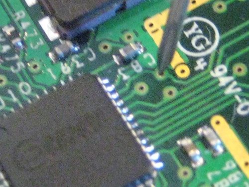
In the photograph above, I've tapped one of three SPI pins of the CC2420 radio chip on a Telos B using a hypodermic syringe. SPI consists of four pins: SCL, MOSI, MISO, and !SS. SCL, the Serial Clock, is output from the master to synchronize communication with the slave. MOSI and MISO are data lins, Master Out Slave In and Master In Slave Out. !SS or Slave Select is an inverted line that indicates the selection of a particular slave chip. Here, we'll only be tapping SCLK and one of the data lines, as two syringes are much easier to hold that four. Ground is shared by USB, so it isn't critical that we tap it.
As seen on my portable scope below, the tapped pin is the SCL, the data clock. The clock stands out because it idles low, and because all pulses in a batch are of regular width. Unlike a system clock, the clock only cycles when data is being transported.
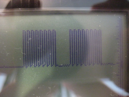
The remaining two pins, in the group of three, are data. As shown on the scope image below, SPI data lines idle high, and bits are measures on edges of the clock.
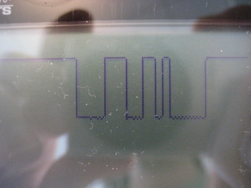
Now that the clock and data lines have been found, it is necessary to sniff the traffic using a bus adapter. Until SPI-sniffing firmware for the Hackaday Bus Pirate becomes available, I will continue to use the Total Phase Beagle I2C/SPI Protocol Analyzer. A screenshot of the Total Phase client follows.
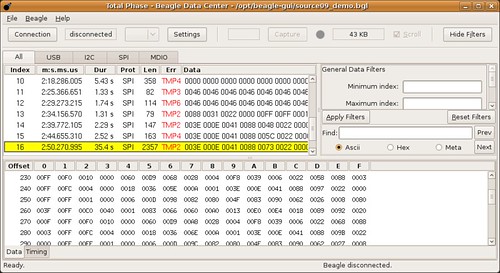
All that remains to identify the key in use, or anything else sent over the bus, is to read the log. I will likely release scripts for doing so at Defcon.
I'm working on a pair of hands-on Zigbee hacking workshops. The first, which I've submitted with Aurélien Francillon to ToorCamp involves the writing of advanced stack overflow attacks for the MSP430 and AVR microcontrollers. The second, which I've submitted to Defcon 17, involves a number of hands-on hardware attacks against Zigbee nodes. Both include the sniffing of AES128 keys from a CC2420 Zigbee radio, a procedure that I demonstrated informally at Source Boston and describe below.
The CC2420 is a popular Zigbee/802.15.4 radio, and it is found in many wireless sensor development kits. We'll be attacking its hardware-accelerated AES128 implementation, by taking advantage of the fact that keys must be loaded over the SPI bus.
In the photograph above, I've tapped one of three SPI pins of the CC2420 radio chip on a Telos B using a hypodermic syringe. SPI consists of four pins: SCL, MOSI, MISO, and !SS. SCL, the Serial Clock, is output from the master to synchronize communication with the slave. MOSI and MISO are data lins, Master Out Slave In and Master In Slave Out. !SS or Slave Select is an inverted line that indicates the selection of a particular slave chip. Here, we'll only be tapping SCLK and one of the data lines, as two syringes are much easier to hold that four. Ground is shared by USB, so it isn't critical that we tap it.
As seen on my portable scope below, the tapped pin is the SCL, the data clock. The clock stands out because it idles low, and because all pulses in a batch are of regular width. Unlike a system clock, the clock only cycles when data is being transported.
The remaining two pins, in the group of three, are data. As shown on the scope image below, SPI data lines idle high, and bits are measures on edges of the clock.
Now that the clock and data lines have been found, it is necessary to sniff the traffic using a bus adapter. Until SPI-sniffing firmware for the Hackaday Bus Pirate becomes available, I will continue to use the Total Phase Beagle I2C/SPI Protocol Analyzer. A screenshot of the Total Phase client follows.
All that remains to identify the key in use, or anything else sent over the bus, is to read the log. I will likely release scripts for doing so at Defcon.
Subscribe to:
Posts (Atom)
